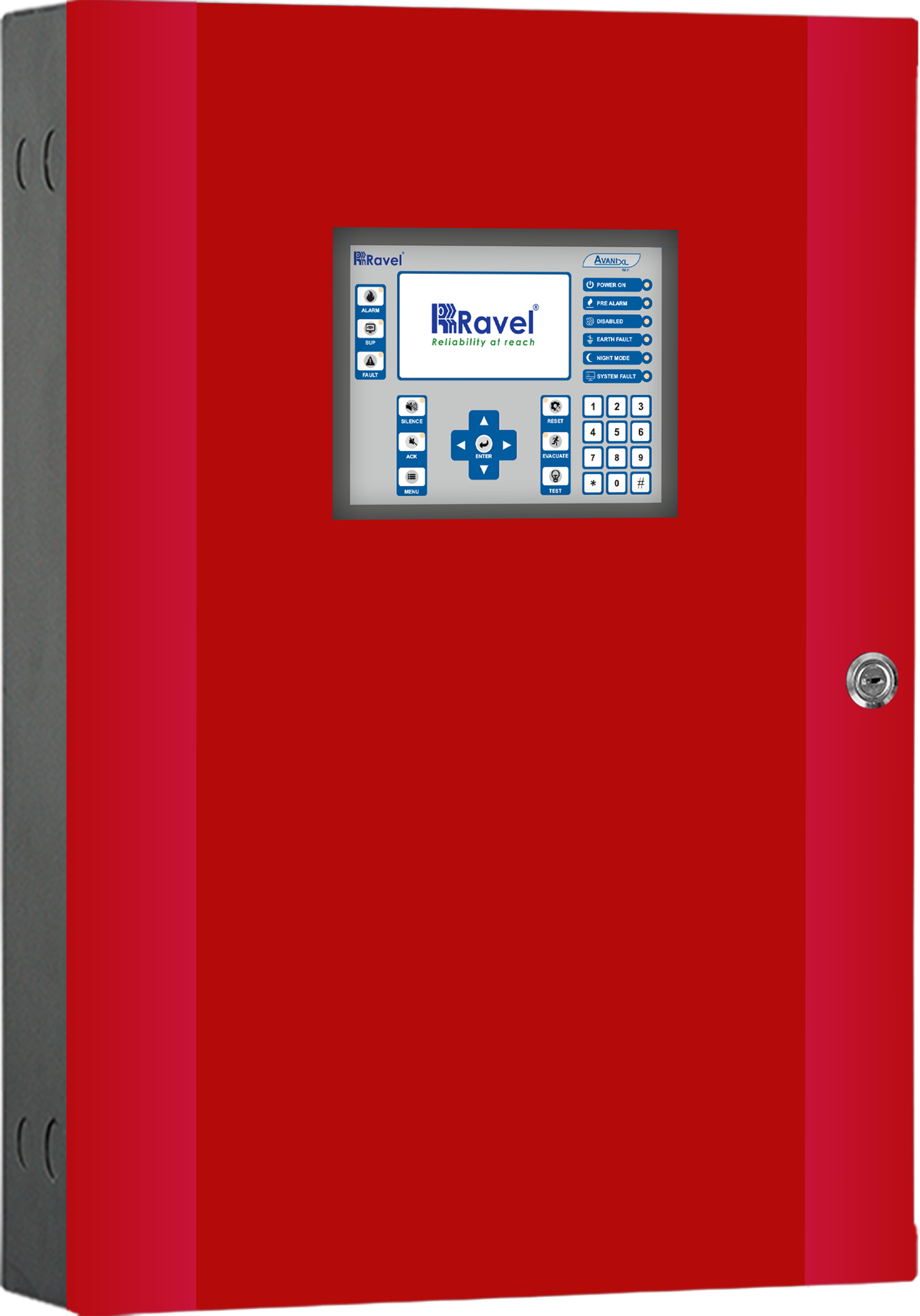
The AARAL is an advanced technology based analogue addressable Fire Alarm Control System designed for medium to large scale infrastructure, ease of use and high reliability with the capacity to support 32,000 devices in any combination. The control panel is designed with an ARM 32-bit microcontroller with high resolution (480 x 272 pixels) 4.3-inch graphical TFT display with a symbolic representation of system status and control keys for easy access. The AARAL is available in two different models as AARAL X4 is expandable up to 4 Loop Addressable FACP and AARAL X8 is expandable up to 8 Loop Addressable FACP.
The panel status shall be visually indicated in unambiguous color with distinguished inbuilt audible tone. This system can operate as a standalone or connect to 16 network nodes with network interface card
| Electrical Specifications | |||
|---|---|---|---|
| Primary Power | 4 Loop
8 Loop |
110 ~ 230VAC, 60 / 50 Hz, (2A @ 110VAC & 1.2A @ 230VAC) Max. 110 ~ 230VAC, 60 / 50 Hz, (2.8A @ 110VAC & 1.4A @ 230VAC) Max | |
| Standby Power | 4 Loop
8 Loop |
24VDC (2 No’s of 12V, 65Ah [Max] panel enclosure can house up to 14Ah sealed lead acid battery) 24VDC (2 No’s of 12V, 65Ah [Max] panel enclosure can house up to 26Ah sealed lead acid battery) | |
| For larger batteries UL listed battery box should be used within 3 meters from the panel by using 2.0 Sq. mm (14AWG) cable | |||
| Charging Circuit | Charging voltage Charging current br Charging Capacity |
28 V, ± 5% nominal 4.3A (max) 65Ah |
|
| Operating Condition | Operating temperature: 0 – 49° C / 32 – 120° F Relative humidity: 93 ± 2% RH (non-condensing) | ||
| Storage Temperature | 0 - 60° C | ||
| Quiescent Curren | 4 Loop
8 Loop |
450mA @ 24V (Max) 500mA @ 24V (Max) |
|
| Alarm Current | 4 Loop
8 Loop |
450mA @ 24V (Max) 500mA @ 24V (Max) |
|
| Relays | Type Quantity Contact Rating Power factor |
Form C 3 No’s 2A @ 30 VDC (Resistive Only) 1.0 |
|
| Notification Appliance Circuits | Operating Voltage NAC current Wiring Style Line Drop EOL resistor |
24 VDC Regulated 1.0 A (Max) per circuit Class B 1.6 V 4K7, ½ watt |
|
| 24VDC Output (Special application) | Quantity Voltage Current |
1 No 24VDC resettable or continuous 500mA (max) | |
| Signaling Line Circuits | Quantity Devices per loop Wiring style Loop Resistance Loop capacitance Loop current |
4 No’s (AARAL X4) & 8 No’s (AARAL X8) 250 No’s / Loop Class A, Class B, Class X 40 Ω (max) 0.6 µf (max) 350 mA (max) |
|
| Remote Input 1 (Initiating Device Circuits) | Quantity Wiring style Operating voltage Alarm current Short circuit current Loop resistance EOL Resistor Standby current |
1 No Class B 17 - 32 VDC 15 – 45 mA 50 mA (max) 40 Ω Max. (each side 20 Ω) 4K7, ½ watt 6.6mA (Including 1.6mA for detectors) |
|
| Remote Input 2 (Input Circuit) | Quantity Wiring style Operating voltage Short circuit current Loop resistance EOL Resistor Standby current |
1 No Class B 4 – 8 VDC 3 mA (max) 40 Ω (max) 4K7, ½ watt 1.3 mA Max. |
|
| RS485 Network (Repeater / RE-PS5) | Nodes Wiring Style Wire type Circuit Length Loop resistance |
8 Class B Shielded Twisted pair. 1.2 Km (Max) 100 Ohms |
|
| NIC Network (Panel to Panel Via NIC) |
Wiring Style Wire type Circuit Length Loop resistance |
Class A and Class B Shielded Twisted pair. 1.2 Km (Max) 100 Ohms |
|
| Mechanical Specification | |||
|---|---|---|---|
| Dimension | 4 Loop
8 Loop |
(400W x 550H x 124D) mm (494W x 720H x 124D) mm |
|
| Wire Size | 2.5 Sqmm (12 AWG) | ||
| Color | White / Red / Black | ||
| IP rating | IP 50 | ||
| Construction(Powder coated finish) | 4 Loop
8 Loop |
Base – 16, Door – 16-gauge CRCA sheet Base – 16, Door – 16-gauge CRCA sheet |
|
| Cable entry |
Top – 7 x Ø 19mm, Side – 2 x Ø 19mm knockouts in the 4Loop cabinet. Top – 7 x Ø 22.5 mm, Side – 2 x Ø 22.5 mm knockouts in the 4 Loop cabinet. Top – 9 x Ø 19mm, Side – 2 x Ø 19mm knockouts in the 8 Loop cabinet. Top – 9 x Ø 22.5 mm, Side – 2 x Ø 22.5 mm knockouts in the 8 Loop cabinet. |
||
| Weight | 4 Loop
8 Loop |
13Kg Approx. 20Kg Approx. |
|